Voltage Source Inverter Circuit Diagram
Single phase voltage source inverters Voltage source inverters (vsi) operation Inverter as high voltage low current source circuit diagram
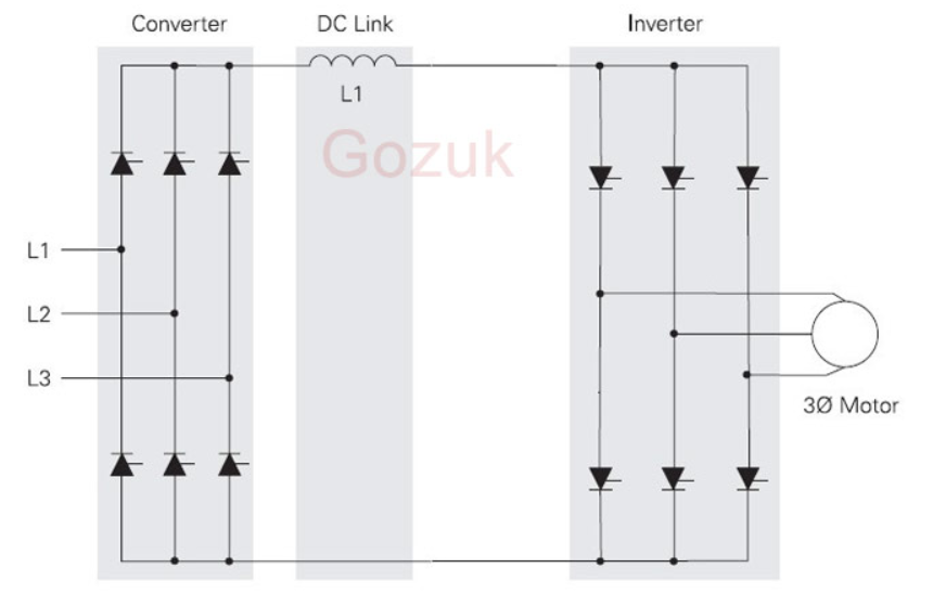
12+ 3 Phase Inverter Circuit Diagram | Robhosking Diagram
High voltage inverter circuit diagram Figure1. single-phase voltage source inverter What is current source inverter? working, diagram & waveforms
What is current source inverter? single-phase current source inverter
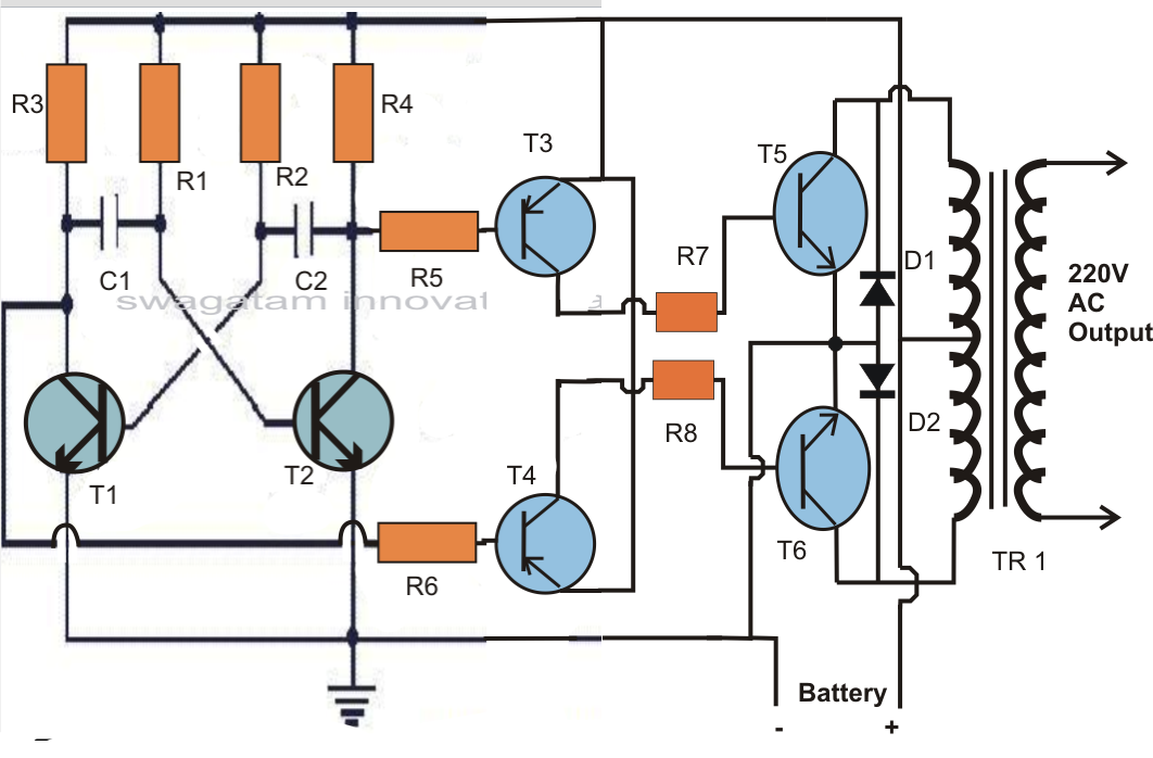
Inverter circuit diagram skema mosquito transformer transistor rangkaian 3v volts input electronic racket stepVoltage source inverter power circuit. Inverter voltage circuit ii schematic simple diagram supply electronic circuits power parts dc produce converter inexpensive negative positive dual singleSimplest power inverter circuit using a single 555 ic.
Inverter conduction inverters switching sine schematics circuitdigestWhat is a voltage source inverter (vsi)? Pwm technique in inverterThree phase inverter circuit diagram.

Electrical video library: v/f control of induction motor
Electrical inverter circuit diagramVoltage source vsi inverter circuit inverters principle operation working power dc Inverter phase circuit diagram principleCircuit diagram of voltage source inverter.
Power circuit of a three-phase voltage source inverter (vsiPin on inverter circuit diagram Inverter phase voltage source three circuit vsi power diagramWhat is current source inverter? definition, control & closed loop.

Charge pump voltage inverter circuit diagram
Operation of 200 watt inverter diagramThree phase voltage source inverter. Operation of single phase inverterWhat is a voltage source inverter (vsi)?.
12+ 3 phase inverter circuit diagramElectrical video library: v/f control of induction motor Homemade power inverter circuit diagramInverter voltage circuit source diagram motor current figure variable frequency.
Inverter 555 circuit ic circuits using power diagram wave bridge output single full simplest square type will homemade explored simple
[diagram] z source inverter circuit diagramCircuit voltage inverter high diagram build circuits power transformer full step using output electronic gr next diagrams Interlocking gate drivers for improving the robustness of three-phaseCircuit diagram of voltage source inverter.
Dc to ac inverter circuit diagramInverter phase circuit three diagram using diode degree thyristor voltage conduction mode thyristors below spike protection designed Voltage inverter circuitDiagram block inverter watt inverters 200watt operation circuits control electronic eleccircuit output projects two figure.

Current inverter source motor induction drive fed control circuit controlled operation dc link closed
Build a high voltage inverter circuit diagramFrank worthley contrarre radioattivo inverter power supply circuit Powersuite page for the voltage source inverter solutionInverter current circuit source diagram figure.
Single phase half bridge inverter explainedInverter voltage high current low source circuit diagram 555 timer power schematics circuits ic using full electronic Phase three gate inverter inverters isolated drivers ti industrial vfd robustness interlocking improving schematic 3phase figure technical.


![[DIAGRAM] Z Source Inverter Circuit Diagram - MYDIAGRAM.ONLINE](https://i2.wp.com/www.researchgate.net/profile/Molay_Roy2/publication/303944710/figure/download/fig1/AS:373537366921216@1466069656936/Circuit-diagram-of-load-resonant-current-source-inverter-for-induction-heating.png)


